
ITO Glass Wire Connections in Electronic Scale Manufacturing: From Structural Design to Ultrasonic Soldering Validation
1. Why Should Electronic Scale Manufacturers Pay Attention to ITO Glass Connection Processes?
Electronic scale manufacturing typically involves load cells, signal-processing circuits, display or control panels, enclosures, and associated wiring. Product structures vary, but when ITO conductive glass is used for touch interfaces, electrodes, or other conductive functions, an electrical connection must be established between the conductive glass area and the external circuitry.
Traditional manufacturing processes may use conductive fabric, conductive snaps, or other intermediate connection structures. These designs can satisfy certain assembly requirements, but they may also increase structural integration requirements, material management tasks, and connection operations.
If the goal is to connect wires directly to the ITO glass surface, ultrasonic soldering can be evaluated as a candidate process. However, implementation should begin with material verification rather than directly transferring conventional PCB soldering procedures to glass.
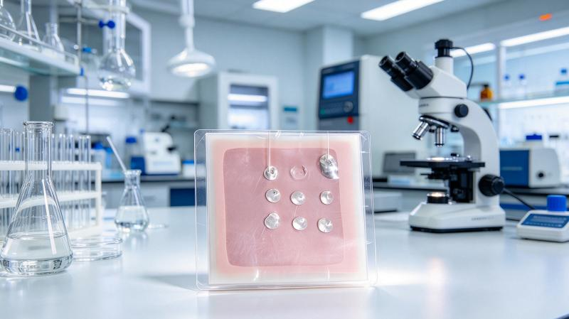
2. Step One: Identify the ITO Glass Structure and Conductive Area
Before soldering, the actual glass structure must be confirmed. Relevant details include the location of the ITO film, the dimensions of the conductive area, the presence of protective layers or other surface coatings, and the locations permitted for soldering.
ITO films are typically very thin. Their load-bearing capability depends not only on the conductive material itself but also on the adhesion between the film and the glass substrate. A smooth-looking glass surface does not, by itself, indicate suitability for direct soldering.
Product designers should provide drawings of the conductive area and confirm that the proposed joint location will not interfere with display, touch, or other functional regions. If an insulating protective layer is present, it must first be established whether direct access to the conductive film is permitted at the intended soldering location.
3. Step Two: Confirm the Wire and Solder System
Wire specifications affect joint dimensions, heat transfer, and mechanical loading. The wire material, diameter, plating, insulation structure, and required preparation of the wire end should all be identified.
At the same time, ITO glass has different wetting characteristics from conventional copper pads. A solder specifically formulated for ultrasonic soldering and suitable for the target materials should therefore be selected and evaluated through sample testing.
The fact that a solder melts when heated does not prove that it can form a reliable connection with ITO. The wetting behavior on the target surface, joint geometry, and coating integrity should be examined, followed by electrical and mechanical testing.
4. Step Three: Establish an Ultrasonic Soldering Procedure
Once the materials have been confirmed, an initial operating procedure can be developed according to the equipment requirements.
4.1 Sample Cleaning and Positioning
Ensure that the soldering area is free of oil, dust, and residues that could interfere with the connection. The cleaning method must be compatible with the ITO film. Solvents and mechanical wiping methods should not be used without first confirming their suitability.
Secure the glass in an appropriate fixture to prevent unnecessary movement or localized stress during soldering.
4.2 Solder and Wire Preparation
Prepare the ultrasonic solder and wire end according to the proposed process. Position the wire within the designated conductive area and prevent solder from spreading to adjacent electrodes or other areas where contact is not permitted.
4.3 Setting Soldering Parameters
Gradually adjust the heating conditions, ultrasonic application time, mechanical contact conditions, and other controllable parameters based on the actual equipment and materials.
Both the ITO film and the glass substrate have limitations regarding thermal and mechanical exposure. Increasing power, extending treatment time, or applying excessive pressure without validation should therefore be avoided.
4.4 Completing the Joint and Allowing It to Cool
After soldering, allow the connection to cool under appropriate conditions before performing visual and electrical inspections. Avoid unnecessary pulling or bending while the joint has not yet stabilized.
5. Step Four: Inspect the Joint and Verify Connection Reliability
After soldering, inspection should cover three main areas.
Visual inspection: Check for cracks, edge chipping, or other glass damage; abnormal changes in the ITO coating; and whether the solder has formed an acceptable joint geometry.
Electrical inspection: Measure connection resistance and confirm compliance with product design requirements. For electronic scales, inspect the complete circuit as necessary to ensure that the connection does not adversely affect signal transmission or functional stability.
Mechanical and environmental testing: Depending on actual operating conditions, perform wire pull tests, bending tests, vibration tests, and any necessary humidity, temperature, or thermal cycling tests. The product design and quality teams should define the specific test methods and acceptance criteria.
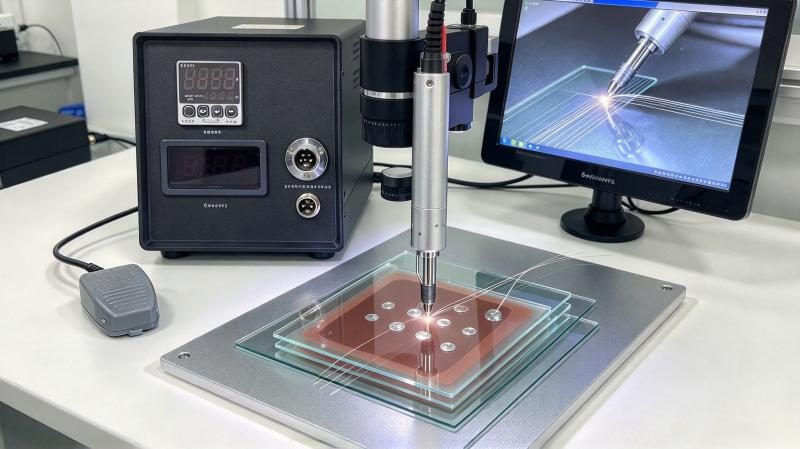
6. Step Five: Evaluate Readiness for Mass Production
Passing laboratory sample tests does not mean that a mass-production process is fully mature. Before implementation, process consistency should be verified across different batches of ITO glass, wire specifications, and operators.
Manufacturers should also assess fixture positioning, cycle time, inspection methods, rework procedures, and operator training. If higher production capacity is required, workstation layout, equipment configuration, and automation feasibility should also be considered.
For electronic scale production lines currently using conductive fabric and conductive snaps, small-scale trials should be conducted without disrupting existing production. Reliability data and actual cost comparisons should guide the decision to switch.
7. Conclusion
Direct wire soldering on ITO glass involves multiple factors, including materials, connection design, soldering processes, and quality verification. Ultrasonic soldering offers a potential route to reducing intermediate connection components, but its suitability for a specific electronic scale must be established through testing with actual materials and comprehensive reliability validation.
U-bonder can work with R&D teams to evaluate sample soldering for ITO glass and wire connections and help determine the next steps in process development.