
Can Ultrasonic Soldering on ITO Glass Achieve Joint Strength Comparable to PCB Solder Pads?
1. The Key Question When Evaluating Direct Wire Soldering on ITO Glass
For manufacturers of electronic scales and other electronic products incorporating ITO conductive glass, one of the main concerns with directly soldering wires to the glass surface is joint strength. Can the joint provide sufficient mechanical retention? Can its reliability approach that of a wire soldered to a conventional PCB pad?
These questions cannot be answered simply by observing how easily soldering can be performed. Joint strength depends on the bonding between the solder and substrate, wire construction, joint geometry, and the mechanical load-bearing capability of the connection area. Because ITO glass and PCB pads have different material structures, the performance of the soldering process must be distinguished from the reliability of the complete connection assembly.
During discussions about related sample applications, U-bonder engineers reported that an ultrasonic soldering iron used with dedicated solder can be evaluated for direct connections between ITO glass and wires. In one application, a customer submitted ITO glass samples for soldering trials, expressed satisfaction with the results, and subsequently purchased equipment. This is encouraging application feedback, but it does not replace standardized pull testing and environmental reliability testing.
2. Why Is It Usually Easier to Develop a Mature Soldering Process for PCB Pads?
PCB pads typically have specifically designed metallic surfaces. Pad dimensions, copper foil structures, surface finishes, and substrate design are selected to meet soldering requirements. With an appropriate solder and process, a well-established metallic connection interface can be formed.
However, the strength of a PCB solder joint is not determined by the solder alone. Pad adhesion, copper thickness, joint geometry, wire loading direction, and thermal cycling conditions can all affect the final result.
ITO glass is different. Its conductive layer is generally a thin film deposited on a glass substrate. Even if the solder makes good contact with the conductive surface, the overall connection may still be limited by the adhesion and load-bearing capability of the ITO film.
In other words, the critical question for direct wire soldering on ITO glass is not only whether the solder adheres, but also whether the conductive film can withstand the mechanical loads transmitted through the wire.
3. How Can Ultrasonic Soldering Help Establish the Connection?
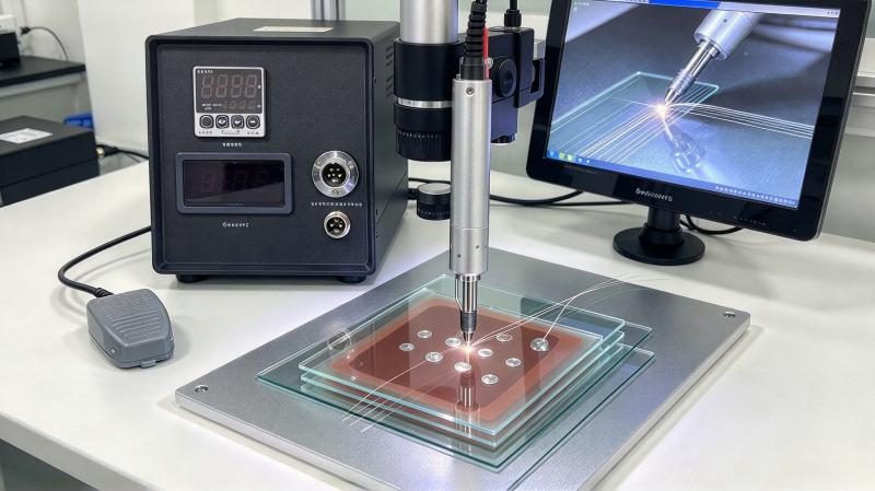
Ultrasonic soldering combines heating with ultrasonic mechanical vibration. When used with a suitable dedicated solder, it can help improve wetting and interfacial contact conditions on certain surfaces.
For ITO glass, the process must address several considerations:
- Solder wetting on ITO: Whether a continuous and effective contact area can be established.
- Heat input: Whether localized thermal stress or changes in coating performance may occur.
- Ultrasonic action and contact pressure: Whether they help establish the connection without damaging the thin film.
- Wire retention: Whether joint dimensions and wire loading cause excessive stress concentration in the connection area.
Under suitable conditions, ultrasonic soldering may enable direct wire connections on ITO glass. However, the achievable mechanical strength must be measured for the actual materials and process. A specific pull-force value cannot be derived from the process principle alone.
4. How to Compare ITO Glass Joints and PCB Joints Scientifically
A fair comparison should use wires of the same specifications, clearly defined loading directions, and consistent test methods for both ITO glass joints and PCB joints.
4.1 Axial Pull Testing
Apply an increasing tensile load along the wire axis and record the load at failure and the failure location.
For ITO glass, particular attention should be paid to distinguishing between the following failure modes:
- Separation between the solder and the conductive layer.
- Delamination of the ITO film from the glass surface.
- Wire breakage near the solder joint.
- Cracking or other damage to the glass.
These failure modes indicate different underlying problems. Even if two sample groups achieve similar maximum pull forces, a group that fails through wire breakage may require a very different process improvement strategy from one that fails through ITO film delamination.
4.2 Peel and Bending Tests
Additional testing should be considered when the product may experience lateral pulling or wire bending during normal use. Wire fixation, bending radius, and loading position can all affect the results.
4.3 Electrical and Environmental Reliability Testing
Meeting the initial connection-resistance requirement does not guarantee stable performance after temperature changes, vibration, or long-term use. Test conditions should reflect the actual product environment. Connection resistance, appearance, and mechanical condition should be checked before and after testing.
5. Can Joint Strength Approach That of PCB Solder Joints?
From a technical perspective, direct wire soldering can produce a connection with practical application value when the ITO glass, wire, dedicated solder, and process conditions are suitable. However, whether the joint can approach the mechanical strength of a particular PCB solder joint must be established through comparative testing.
PCB solder joints themselves vary in design and strength. Without clearly specifying the pad structure, wire dimensions, test direction, and test standard, no universal conclusion about relative strength can be made.
For electronic scale manufacturers, a more practical approach is to use the existing connection method as a baseline, determine whether ultrasonic-soldered samples meet product requirements, and compare the failure modes, production repeatability, and environmental stability of both solutions.
6. Conclusion: Make Decisions Based on Failure Modes and Test Data
The main risk in direct wire soldering on ITO glass may not be the strength of the solder itself, but the bonding between the thin-film conductive layer and the glass substrate. Testing should therefore examine the solder joint, ITO coating, and glass substrate rather than recording only a single pull-force value.
U-bonder has received positive preliminary feedback from customers who evaluated sample connections. Manufacturers seeking to confirm joint strength are encouraged to provide their actual glass and wire samples for initial soldering trials, followed by mechanical, electrical, and environmental validation based on their product requirements.