
PCB Pads vs. Ultrasonic Soldering Irons: Why Direct Wire Soldering on ITO Glass Requires a Different Process Approach
1. Why Can’t Conventional PCB Soldering Experience Be Applied Directly to ITO Glass?
Soldering wires to PCB pads is a common process in electronics manufacturing. Engineers typically optimize the process based on pad surface finish, solder type, soldering iron temperature, and soldering time.
However, when the connection target changes from a metallic PCB pad to ITO conductive glass, the existing process must be reevaluated. The conductive area on ITO glass is generally a thin film attached to a glass substrate, rather than a relatively robust metallic pad with the same structural and load-bearing characteristics.
Consequently, even when the same wire and solder are used, the two materials cannot be assumed to exhibit the same wetting behavior or mechanical strength.
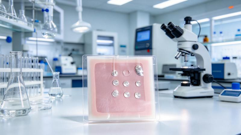
2. Structural Advantages of PCB Pads
PCB pads are generally designed specifically for component assembly or wire soldering. The surface metal layer, pad dimensions, copper foil adhesion, and substrate material collectively determine their suitability for soldering.
When solder adequately wets the pad and forms a suitable joint, mechanical loads are transferred through the solder joint, pad, and substrate structure. Therefore, PCB joint evaluation must consider more than the solder itself. Pad detachment, copper foil delamination, and wire breakage must also be examined.
This is one reason PCB soldering can often be supported by mature process specifications: the material system, pad design, and soldering methods typically have a well-established engineering basis.
3. The Specific Challenges of ITO Glass
ITO films must provide electrical conductivity while maintaining transparency. Film thickness, surface treatment, and adhesion can all affect the results of direct wire soldering.
Compared with PCB pads, ITO glass introduces several additional considerations.
First, surface wetting. Conventional solder may not achieve ideal wetting on an untreated ITO surface. Suitable dedicated solder and process methods therefore need to be evaluated.
Second, thin-film load-bearing capability. Even when a solder joint forms, mechanical loads may be transferred to the interface between the ITO film and glass. If film adhesion is insufficient, localized delamination may occur.
Third, thermal shock risk. The thermal conduction characteristics and localized stress conditions of glass differ from those of PCB substrates. Rapid localized heating or excessive temperature gradients may cause damage.
Fourth, the process window. Soldering temperature, ultrasonic application time, contact pressure, and tool condition must be optimized for the actual samples. Conventional PCB soldering parameters should not simply be copied.
4. Process Differences Between Ultrasonic and Conventional Soldering Irons
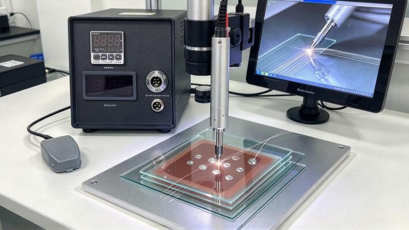
A conventional soldering iron primarily supplies heat to melt the solder, relying on wetting of the target surface to form the connection. An ultrasonic soldering iron introduces ultrasonic mechanical vibration in addition to heating and uses an appropriate dedicated solder to improve soldering conditions for specific materials.
For ITO glass, ultrasonic action provides a way to investigate direct connection processes that may be difficult to achieve using conventional soldering methods. Nevertheless, reliable joint formation still depends on the properties of the ITO film, solder compatibility, and operating parameters.
An ultrasonic soldering iron should therefore not be regarded as a universal replacement for every conventional soldering iron. It is an alternative process option for specific material-joining challenges.
5. How to Design a Meaningful Comparative Test
Manufacturers wishing to compare PCB joints with ITO glass joints can develop a test plan covering the following aspects:
- Select wires with clearly defined specifications and keep wire material, diameter, and end preparation consistent.
- Document the PCB pad surface finish and the ITO glass coating conditions, clearly identifying the differences between the two substrates.
- Optimize the appropriate soldering process for each material rather than forcing both to use identical parameters.
- Apply a consistent pull-test method and record both the maximum load and the failure location.
- Examine joint appearance, contact resistance, coating damage, and relevant environmental test results.
- Validate the results using repeated samples and assess data variation rather than drawing conclusions from a single specimen.
The objective of a comparative test is not to prove that one process must always outperform the other, but to determine whether each approach meets the requirements of the specific product.
6. How Should Engineers Interpret the Claim That a Joint Is “Comparable to a PCB Solder Joint”?
During preliminary sample evaluations, engineers have indicated that an ultrasonic soldering iron and dedicated solder can be used to establish wire connections on ITO glass, with the potential to achieve results relevant to common PCB soldering applications.
This can serve as a starting point for process development. However, before describing the result as “comparable” in a formal technical specification or making a reliability commitment to a customer, the comparison target and test standards must be clearly defined.
For example, are the two connections being compared in terms of initial pull strength, performance after bending, or electrical stability after temperature and humidity cycling? These measurements may lead to different conclusions.
7. Conclusion
The structural differences between PCB pads and ITO glass mean that the same soldering experience cannot be applied to both without modification. An ultrasonic soldering iron combined with dedicated solder provides a technical approach worth evaluating for direct wire soldering on ITO glass. However, process feasibility and mass-production reliability must still be confirmed using actual materials and standardized testing.
HLSCI can help evaluate sample soldering based on customer-specific ITO glass and wire specifications, and discuss suitable process solutions covering soldering parameters, connection strength, and subsequent validation requirements.