Conductive Fabric and Conductive Snaps vs. Ultrasonic Soldering: Comparing Wire Connection Methods for ITO Glass
1. Why Reevaluate Traditional Connection Methods?
In electronic scales and electronic modules incorporating ITO conductive glass, conductive fabric, conductive snaps, and similar connection structures can establish electrical connections between the conductive glass area and external circuitry. These solutions offer the advantage of a separate intermediate connection structure that can be integrated into the product assembly design.
From a manufacturing perspective, however, intermediate connections may introduce additional materials, assembly steps, and space requirements. For example, conductive fabric must be accurately positioned and maintain stable contact, while conductive snaps require compatible structural features. Connection components may also be affected by assembly tolerances, long-term mechanical loads, and changes at contact interfaces.
These considerations do not mean that traditional methods are inherently unreliable. Rather, when a product requires fewer components, a simpler internal structure, or a revised assembly process, direct wire connection to ITO glass becomes an alternative worth evaluating.
2. Characteristics of Traditional Conductive Fabric and Conductive Snap Connections
2.1 Conductive Fabric Connections
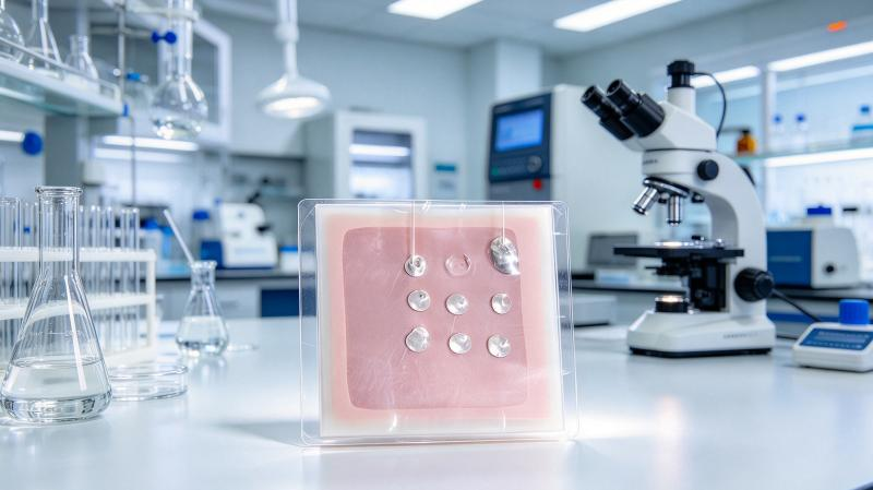
Conductive fabric is commonly used as a flexible conductive intermediate material. It can accommodate certain spatial constraints and assembly requirements. Actual connection quality depends on the fabric material, contact pressure, positioning accuracy, surface condition, and fixing method.
If contact pressure changes over time or the assembly position deviates from its intended location, connection resistance and mechanical stability may also change. The fixing structure, contact area, and operating environment must therefore be considered during product design.
2.2 Conductive Snap Connections
Conductive snaps establish connections through a mechanical structure and are suitable for products designed with dedicated installation space and mounting positions. Their advantages include a clearly defined connection structure and, in some designs, relatively convenient assembly or disassembly.
However, conductive snaps require appropriate dimensional tolerances, mounting strength, and local load management. Additional components may constrain product layout when internal space is limited. Products requiring a particularly thin internal structure may need further design adjustments.
3. How Does Ultrasonic Soldering Differ?
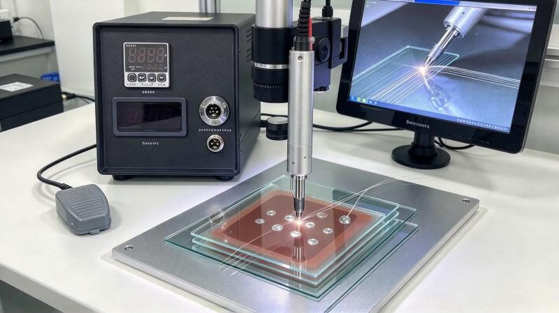
Ultrasonic soldering combines heating with ultrasonic mechanical action and uses suitable solder formulated for ultrasonic soldering to create a direct solder joint between the ITO conductive area and the wire.
Compared with conductive fabric or conductive snap connections, the main difference lies in the connection interface and assembly structure.
Traditional solutions transfer current through an intermediate conductive material or mechanical contact structure. Direct soldering, by contrast, requires effective bonding between the solder and conductive coating, together with sufficient mechanical retention of the wire.
If validation confirms that the process meets product requirements, direct soldering may reduce certain intermediate components and assembly steps. However, it also introduces new technical requirements: the ITO coating must withstand the thermal and mechanical effects of soldering, process parameters must remain stable, and the resulting joint must provide adequate mechanical reliability.
4. How Should the Two Processes Be Compared Fairly?
| Comparison Factor | Conductive Fabric and Conductive Snaps | Direct Ultrasonic Soldering |
|---|---|---|
| Connection principle | Intermediate conductive material or mechanical contact | Solder joint formed with the conductive area |
| Structural design | Requires space for intermediate connection components | May simplify the connection structure |
| Key process considerations | Positioning, contact pressure, and fixing method | Solder wetting, coating integrity, and heat input |
| Main risks | Changes in contact conditions and assembly deviations | Coating damage, joint detachment, and thermal damage to glass |
| Repair method | Depends on connector design; some configurations are easy to disassemble | Rework must be evaluated for its effects on the glass and coating |
| Mass-production requirements | Consistent assembly and contact conditions | Consistent soldering parameters, operating procedures, and joint quality |
The table compares process characteristics; it does not establish that one method is superior for every product. Actual performance depends on the glass, coating, wire, connection structure, and operating environment.
5. Cost and Production Efficiency Involve More Than Individual Component Prices
If direct soldering can eliminate conductive fabric, conductive snaps, or associated fixing components, it may reduce certain material costs and assembly operations. At the same time, manufacturers must account for equipment investment, cycle time, inspection methods, rework costs, and process training.
For example, a traditional connection method may already have a mature production workflow, whereas direct soldering may require parameter development and reliability validation during initial implementation. Manufacturers should therefore compare the total cost per unit across the complete production process rather than simply comparing equipment prices with connector material costs.
6. How to Decide Whether to Switch Processes
A practical evaluation can follow these steps:
- Identify the actual limitations of the existing connection method, such as space requirements, assembly steps, contact stability, or material costs.
- Provide the existing ITO glass, wire, and relevant structural information for ultrasonic soldering sample trials.
- Evaluate both solutions using consistent mechanical, electrical, and environmental test standards.
- Compare assembly cycle time, operating complexity, yield, rework procedures, and total cost.
- Conduct a pilot production run using representative samples before deciding whether to implement the process in mass production.
For electronic scale manufacturers, ultrasonic soldering should not be viewed merely as a change of soldering equipment. It should be evaluated as a potential improvement to the entire connection structure and manufacturing workflow.
To compare conductive fabric, conductive snaps, and direct wire soldering on ITO glass, contact U-bonder to discuss sample testing and process validation.