
Ultrasonic Chip Pin Soldering
Ultrasonic Chip Pin Soldering- Chip Soldering – Sonic4lab
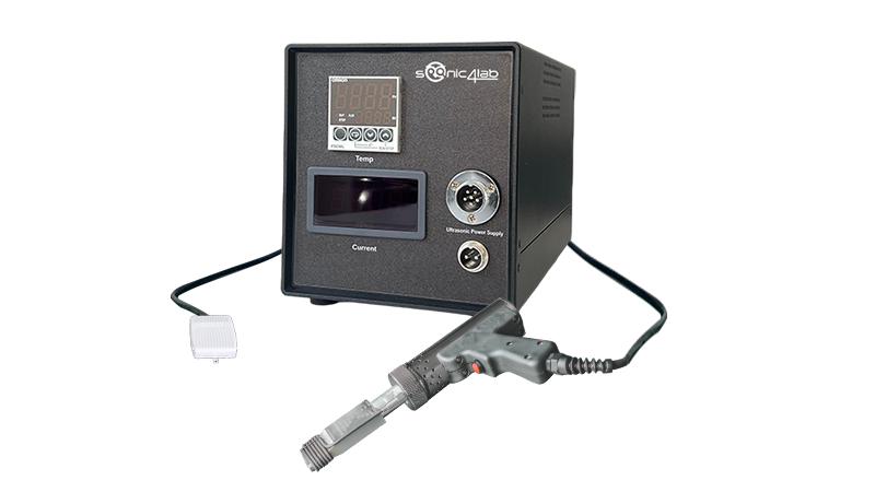
In the world of electronics manufacturing, connecting chip pins to the circuit board is a core step, and the soldering iron is the key tool for achieving this connection. The seemingly simple soldering action actually involves precise control of temperature, pressure, and timing; the quality of each solder joint directly determines the stability of the electronic device.
Preparation before soldering is fundamental to success. First, select a suitable soldering iron; an adjustable temperature model is preferred. Depending on the thickness and density of the chip pins, setting the temperature between 300-350℃ is most suitable. Simultaneously, prepare matching solder wire, flux, tweezers, and a magnifying glass. If there is an oxide layer on the chip pins and circuit board pads, wipe them clean with alcohol wipes, and lightly polish if necessary to ensure conductivity and wettability during soldering.
Core soldering steps must follow standardized procedures. For chips with less dense pins, the “diagonal fixing method” can be used: use tweezers to precisely position the chip, and first spot solder a small amount of solder on two diagonally opposite pins to firmly fix the chip to the pads, preventing displacement during subsequent soldering. When soldering the remaining pins, you can choose between spot soldering or drag soldering. Spot soldering is suitable for chips with fewer pins. Contact the pin and pad simultaneously with the soldering iron tip for 1-2 seconds. Once the temperature reaches the target, insert the solder. Allow the solder to naturally coat the joint, then immediately remove the tool. Drag soldering is more suitable for multi-pin chips. First, apply a suitable amount of flux to the pins. Dip the soldering iron tip in a small amount of solder and smoothly drag it along the pin arrangement. Use the flux to evenly coat each pin with solder. The action should be continuous to avoid prolonged contact that could damage the chip.
Post-soldering inspection is just as important as defect handling. Observe each solder joint with a magnifying glass. An ideal solder joint should have a smooth, concave surface, completely covering the pad without burrs or bridging. If bridging occurs, use desoldering wick with the soldering iron to remove excess solder. If the solder joint is dull or has cold solder joints, it needs to be reheated and repaired. It is important to note that after soldering, allow the solder joint to cool naturally. Do not blow air or pour water to accelerate cooling, as this can easily lead to cold solder joint defects.
The maintenance and usage precautions of soldering irons are also crucial. During use, the soldering iron tip should be wiped with a high-temperature sponge regularly to remove oxide layers and apply a thin layer of tin to prevent poor heat conduction. Never press forcefully on chip leads during soldering; the heating time for a single lead should not exceed 3 seconds to prevent damage to the chip’s internal circuitry from high temperatures. When desoldering, the old solder must be completely melted before gently removing the chip with tweezers; never pry it forcefully to avoid damaging the pads.
Soldering chip leads is a combination of skill and patience; precise control of the soldering iron is key. From preparation to soldering and subsequent inspection, every step requires meticulous attention. Mastering this skill not only enables you to complete electronic projects but also allows you to deeply appreciate the rigor and focus behind precision manufacturing.
If you want to purchase equipment, please click here.
