
Why Is Direct Wire Soldering on ITO Glass So Difficult? Wetting, Coating Damage, and Connection Reliability
1. The Challenge Is Not Simply Whether the Solder Can Melt
For electronic scales, touch panels, and other products using ITO conductive glass, engineers may want to connect wires directly to the conductive area on the glass surface to eliminate intermediate connection structures such as conductive fabric and conductive snaps.
At first glance, this may appear to be a straightforward task: soldering a wire to a conductive surface. In practice, however, ITO glass has a different material structure from conventional metallic solder pads. Direct wire soldering must address not only solder wetting but also thin-film protection, localized heat input, and the ability of the connection to withstand mechanical loads during actual use.
Focusing only on whether the solder melts or adheres to the surface can overlook the interfacial issues that determine long-term reliability.
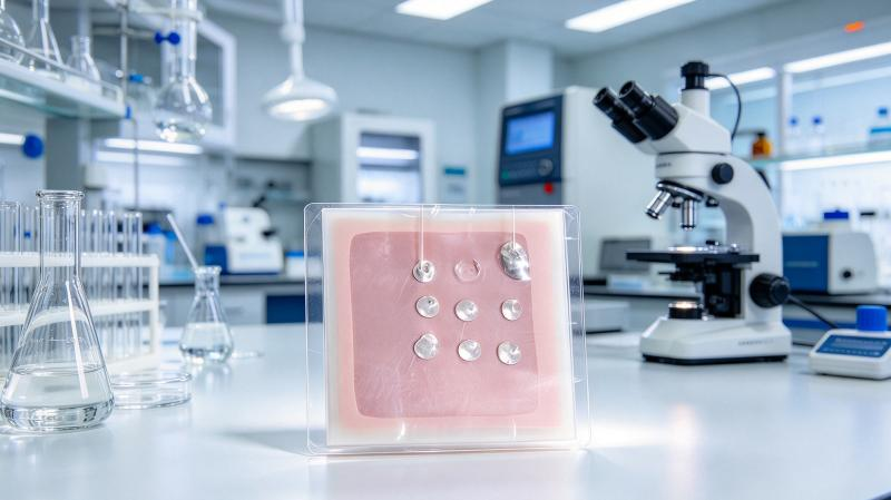
2. Challenge One: ITO Surfaces Differ from Conventional Metallic Solder Pads
ITO is a transparent conductive oxide film typically deposited on a glass substrate. Conventional electronic solder does not necessarily achieve ideal wetting on an untreated ITO surface.
Even when the solder melts, an effective connection with the conductive film may not form. If interfacial contact is inadequate, the joint may detach under relatively small external forces or exhibit unstable contact resistance.
Direct wire soldering therefore begins with evaluating solder compatibility with the ITO surface and determining whether a specialized soldering process is required.
3. Challenge Two: The Conductive Layer Is Thin, and Connection Strength May Be Limited by the Interface
Conventional PCB pads have specifically designed metallic structures, whereas the thickness and adhesion of an ITO film may be constrained by the manufacturing process used for the glass product.
When a wire is pulled or bent, the load is transferred through the solder joint to the conductive film. If the solder connection is strong but adhesion between the film and glass is insufficient, failure may occur at the coating interface.
This means that the mechanical reliability of an ITO glass joint cannot be assessed solely by considering solder strength. The integrity of the conductive film, the condition of the glass, and the design of the overall connection must also be examined.
4. Challenge Three: Glass Is Sensitive to Localized Heat Input
Soldering requires heat, but the thermal conductivity, thermal expansion, and localized stress conditions of glass differ from those of metallic substrates. Inappropriate heating may create large local temperature gradients, increasing thermal stress and the risk of glass damage.
For glass with functional coatings, the effects of temperature on film performance and adhesion must also be considered.
Process development should therefore avoid relying solely on higher temperatures to solve wetting problems. A more appropriate approach is to evaluate the solder system, heating conditions, application time, and mechanical contact conditions together to identify a suitable process window for the specific materials.
5. Why Is an Ultrasonic Soldering Iron Worth Evaluating?
An ultrasonic soldering iron combines conventional heating with ultrasonic mechanical vibration and uses suitable solder formulated for ultrasonic soldering. For certain surfaces that are difficult to wet using conventional methods, this combination can help improve interfacial contact conditions and provide an alternative approach to direct soldering.
Compared with intermediate connection methods such as conductive fabric and conductive snaps, direct wire soldering may reduce certain components and assembly operations if testing confirms that the process meets product requirements.
However, the technology has limitations. The ITO film structure, surface treatment, wire material, and solder composition can all affect the outcome. Excessive ultrasonic action, prolonged heating, or inappropriate contact pressure may also damage the coating or produce defective joints.
The value of this technology lies in offering a connection method that can be developed and tested, not in guaranteeing that every type of ITO glass can be soldered directly.
6. How to Move from Laboratory Testing to Stable Production
A practical validation plan can be divided into four stages.
Stage 1: Material Identification
Identify the glass substrate, ITO conductive area, surface coatings, wire material, and wire diameter. Confirm whether direct contact with the conductive area is permitted and whether protective layers or other restrictions are present.
Stage 2: Sample Process Development
Conduct small-scale trials using a suitable ultrasonic soldering iron and dedicated solder. Adjust the process conditions systematically. Each trial should record the solder type, sample details, parameters, and operating method rather than relying solely on operator experience.
Stage 3: Connection Quality Validation
Inspect joint appearance, glass and coating integrity, initial resistance, and mechanical strength. For products such as electronic scales, evaluate potential effects from vibration, wire bending, and temperature changes under realistic operating conditions.
Stage 4: Mass-Production Suitability Assessment
Use repeated samples and different material batches to confirm process consistency. Evaluate cycle time, positioning fixtures, quality inspection, and rework procedures. If direct soldering is intended to replace an existing conductive fabric and conductive snap solution, compare total production costs and finished-product reliability as well.
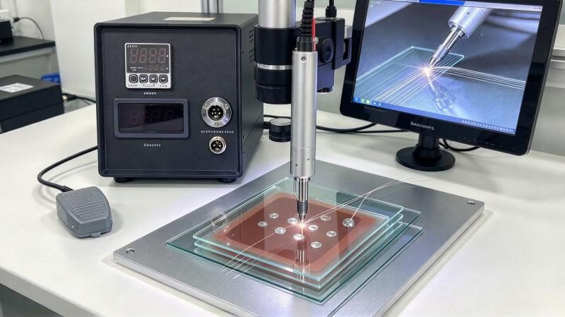
7. Evaluating Actual Samples Is More Effective Than Discussing Principles Alone
For direct wire soldering on ITO glass, U-bonder has received customer-submitted samples and conducted soldering trials using an ultrasonic soldering iron and dedicated solder. The customer was satisfied with the sample results and subsequently purchased equipment for continued application.
This indicates that the approach is worth further investigation, although each combination of glass coating and wire still requires its own evaluation. For manufacturers, the most effective next step is generally to provide actual glass and wire samples, define the mechanical strength and electrical performance requirements, and then develop a targeted validation plan.
Conclusion: The main challenge in direct wire soldering on ITO glass lies at the interface, not simply in the soldering operation itself. By combining an appropriate ultrasonic soldering process with material compatibility assessment and reliability testing, manufacturers may be able to develop a direct connection method better suited to their specific product designs.
U-bonder welcomes discussions with R&D teams working on electronic scales, electronic hardware, and conductive glass assemblies regarding sample testing and process development.